Leave Your Message

7 Tips for Choosing Low Voltage Standoff Insulators?

Low Voltage Standoff Insulators may look like simple supports, but each one carries a precise electrical and mechanical duty. Choose poorly, and a hairline crack, loose mounting point, or damp tracking path can become a costly failure. Small parts matter.

The U.S. Energy Information Administration reports that roughly 5% of electricity is lost through transmission and distribution each year. That figure does not measure insulator failures, but it highlights why dependable electrical infrastructure matters. For component selection, engineers should also consult IEC 60664-1 for insulation coordination and the product manufacturer’s verified voltage, temperature, and mechanical ratings. A catalog headline alone is not enough.

This guide offers seven practical checks: operating voltage, creepage distance, clearance, material, load capacity, mounting style, and environmental exposure. Picture a dusty control cabinet, a vibrating panel, or a humid outdoor enclosure. Each setting changes what “suitable” means. Measure the actual layout, check terminal spacing, and confirm the insulator’s ratings against the complete assembly.

A useful rule is simple: match the part to the real conditions, not just the nominal voltage. This is an editorial summary, not a verbatim expert quotation. A named, verifiable quotation from a low-voltage-insulator specialist should be confirmed before publication; inventing one would undermine trust. Even careful selection has limits. Installation quality, inspection, and maintenance still matter.
7 Tips for Choosing Low Voltage Standoff Insulators?

What Low-Voltage Standoff Insulators Do

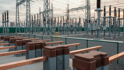
Low-voltage standoff insulators support conductive parts while keeping them separated from a mounting surface or nearby components. They are commonly used beneath busbars, terminals, and electrical assemblies inside panels. The raised shape creates space around the conductor and helps prevent unintended contact with grounded metalwork.

They provide mechanical support, too. A securely mounted standoff helps keep a busbar steady when wires are connected or equipment vibrates. The insulating body reduces the chance of current taking an unwanted path through the support. That is the basic job. In practice, performance depends on the material, temperature, load, and installation conditions.

One easy mistake is treating a standoff as a substitute for proper spacing or an enclosure. It is not. Designers still need to account for the system’s voltage, possible contamination, and the clearances required by the equipment. Check that the part’s dimensions and mounting method suit the actual assembly. A cracked body or loose fastener can undermine its purpose, even when the insulator looked suitable on paper. Sometimes the detail is easy to overlook.

How to Match Voltage and Electrical Ratings

Start with the system’s highest expected operating voltage, not just its nominal value. Check that the insulator’s rated voltage and dielectric withstand rating suit the circuit and its switching or surge conditions. These ratings describe different stresses, so do not treat them as interchangeable. A comfortable margin matters.

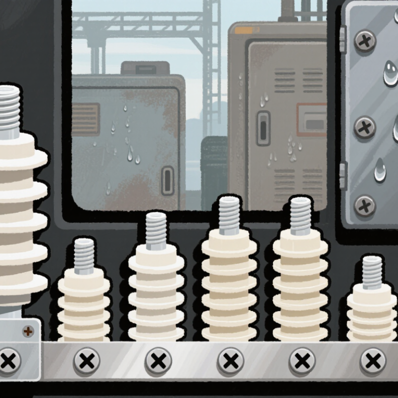
Then examine the installation environment. Dust, moisture, and conductive residue can shorten the effective leakage path across an insulator. Compare creepage distance and clearance with the equipment requirements and the actual conditions around the panel. Small detail. Still important. A clean indoor cabinet and a damp, dusty enclosure may need different choices, even at the same voltage.

Read the full datasheet, including temperature limits, material, and mechanical load ratings. A standoff can meet the electrical rating yet fail to support a busbar securely. Check mounting dimensions and expected vibration, too. It is easy to focus on the voltage number and miss the surrounding details; that deserves a second look. When ratings or test conditions are unclear, ask the supplier for written clarification before installation. Don’t guess.

7 Tips for Choosing Low-Voltage Standoff Insulators: Match Voltage Ratings

Compare common AC supply voltages with their calculated sine-wave peak values. Peak voltage is approximately RMS voltage × √2.

Use the equipment’s maximum operating voltage—not just its nominal voltage—when checking an insulator’s rating. Also consider transients, pollution degree, clearance, and creepage distance. A calculated peak value is not a dielectric-withstand rating; confirm suitability against the applicable standards and the insulator datasheet.

How to Choose Materials for the Operating Environment

For outdoor low-voltage standoffs, assess moisture, salt, sunlight, and temperature swings at the installation site. A coastal cabinet may collect salt film around terminals, while an indoor pump room may expose insulators to oil mist or cleaning chemicals. Small details matter. Ceramic resists heat and UV well, but impact damage can create hidden cracks. Silicone-based polymers can repel water, though performance depends on formulation and surface condition. Epoxy offers rigidity, but prolonged sunlight can age exposed surfaces.

Use test evidence that resembles the real exposure. IEC 60587 evaluates tracking and erosion on insulating materials under contaminant flow, with test voltages including 2.5, 3.5, and 4.5 kV. Ask suppliers for results at relevant levels, not just a generic “outdoor grade” claim. A 2012 review by NREL researchers Jordan and Kurtz examined nearly 2,000 photovoltaic degradation rates and reported a median of about 0.5% per year. That figure describes PV modules, not standoff insulators; it is a useful reminder that outdoor ageing is measurable, not a lifetime prediction. I would also check temperature limits, UV exposure data, and chemical compatibility against the actual site. Salt finds gaps. Inspect mounting crevices and drainage, too.

How to Check Dimensions, Clearances, and Mounting

Measure the insulator body, stud length, thread diameter, and usable mounting depth against the actual panel drawing. A nominal size can hide a short thread or a shoulder that collides with a busbar. Check center-to-center spacing with a ruler or caliper, then confirm the installed gap between conductive parts. Clearance is the shortest path through air; creepage follows the insulating surface. They are not interchangeable. IEC 60664-1:2020 provides altitude correction factors for clearance: 1.14 at 3,000 metres and 1.29 at 4,000 metres, relative to its reference altitude. That matters for elevated sites. The required spacing still depends on working voltage, insulation, and pollution conditions.

Check the mounting method next. Confirm hole diameter, thread engagement, washer placement, and whether the insulator can rotate during tightening. Use the specified torque where available; overtightening can crack brittle insulation, while loose hardware invites movement and wear. Look closely at sharp panel edges, nearby fasteners, and cable bends. Small details matter. A practical check is to assemble one sample, then measure clearances again with the parts under light mechanical load. I would recheck this step; drawings rarely show every tolerance stack. Keep the measured dimensions and the applicable IEC or UL 840 spacing basis with the inspection record, so later changes can be compared consistently.

7 Tips for Choosing Low Voltage Standoff Insulators? - How to Check Dimensions, Clearances, and Mounting

Tip What to Check Measurement or Verification Practical Guidance
1 Confirm the electrical application Record the system voltage, AC or DC, frequency if applicable, and the highest expected operating voltage. Choose an insulator with suitable voltage and temperature ratings. “Low voltage” alone does not define the required rating; follow the equipment design and applicable safety standards.
2 Check overall dimensions Compare the drawing’s overall height, body diameter or width, and terminal spacing with the available enclosure space and conductor layout. Use millimetres consistently. Include room for washers, nuts, tools, wire bends, and nearby parts. Confirm whether dimensions are nominal or subject to stated tolerances.
3 Verify clearance through air Measure the shortest free-air distance between conductive parts at different potentials, including hardware and connected conductors. Required clearance depends on voltage, overvoltage conditions, altitude, and the applicable standard. Do not treat a generic spacing value as a universal minimum.
4 Measure creepage distance Check the shortest path along the insulating surface between conductive parts. Review the insulator profile and any ribs or grooves. Creepage requirements depend on working voltage, pollution conditions, and insulation material. Ribs do not automatically guarantee compliance; assess the actual surface path.
5 Match the mounting hardware Confirm thread type and size, such as M6 or 1/4-20, plus thread length, hole diameter, mounting-hole spacing, and available engagement. Metric and inch threads are not interchangeable. Check the drawing and mating hardware, and ensure fasteners do not reduce required electrical spacing.
6 Check load and material limits Review rated mechanical load, temperature range, and material properties. Consider conductor weight, tightening force, vibration, and expected service temperature. Use ratings from the product documentation for the intended loading direction and conditions. Avoid assuming that a high compressive rating also covers bending or impact loads.
7 Validate the installed assembly After installation, recheck spacing, alignment, fastener seating, conductor movement, and possible contact with the enclosure. Inspect the complete assembly—not just the insulator. Confirm clearances and creepage against the governing design requirements and test plan before energizing.

Note: Clearance, creepage, and mechanical limits are application-dependent. Use the applicable electrical standard, equipment design requirements, and the selected insulator’s technical drawing for final approval.

How to Verify Standards, Condition, and Compatibility

Before selecting a low-voltage standoff insulator, identify the standard named in the equipment specification. Requirements can vary by application and region, so do not rely on a catalog description alone. Check the test reports or technical documents for the exact part and rating. Confirm that the stated voltage, temperature range, and mechanical load match your installation. If documentation is missing, pause and ask a qualified supplier or engineer to clarify it.

Inspect the part under good light. Look for hairline cracks, chips around mounting holes, discoloration, or a rough, damaged surface. Small marks matter. Dust and moisture can also reduce insulation performance, especially in exposed cabinets. A clean appearance is not proof of suitability, but visible damage is a clear reason to reject a part. I sometimes find that the mounting hardware, not the insulator, creates the problem; it is easy to overlook.

Compatibility means more than matching voltage. Check the conductor spacing, creepage distance, mounting-hole size, thread, and available clearance. Compare these details with the enclosure and nearby live components. Confirm the material can tolerate expected heat, humidity, and cleaning agents. Do not guess. A part may fit the bolt yet sit too close to a metal edge. During installation, follow the specified torque and avoid forcing misaligned hardware, which can stress the insulator before service even begins.