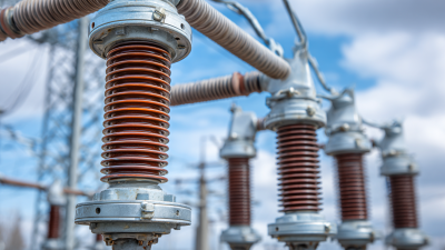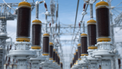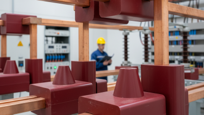
Choosing Low Voltage Standoff Insulators in 2026 starts with understanding the job each insulator must perform. It must support a conductor, maintain electrical clearance, and withstand expected mechanical stress. A compact part may look suitable on a drawing, yet fail to fit the real assembly. Measure the mounting pattern and available space before comparing products.
Voltage rating is only one part of the decision. Check the manufacturer’s data for operating voltage, dielectric strength, creepage distance, temperature range, and load limits. Then consider the installation environment. Dust, moisture, heat, vibration, and chemical exposure can affect material performance over time. Small details matter. A clean indoor cabinet and a damp outdoor enclosure do not present the same conditions.
Material choice also deserves careful review. Ceramic, polyester, and other engineering materials can differ in strength, weight, temperature tolerance, and resistance to tracking. Match the material and hardware to the application, rather than choosing by appearance or price alone. Confirm that the product’s dimensions and ratings align with the equipment design, and consult qualified engineering support when requirements are unclear. Datasheets are useful, but they cannot resolve every installation detail. That part takes judgment. In practice, teams sometimes overlook access for tightening or inspection; it is an easy mistake to repeat. This guide outlines a practical way to compare Low Voltage Standoff Insulators, ask better questions, and document the reasons behind a selection.
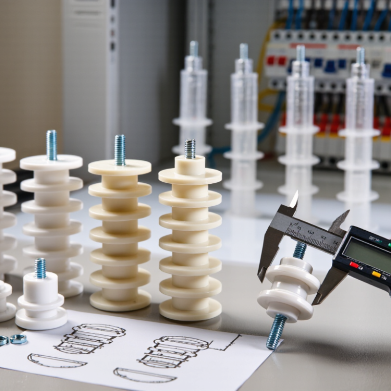
A low-voltage standoff insulator supports a conductor while separating it from a grounded panel or frame. Its job is both electrical and mechanical. It maintains clearance, limits the risk of unintended contact, and holds the conductor steady under normal service loads. The required voltage rating is only one part of the choice. Check the expected working voltage, brief voltage surges, and the insulation’s creepage and clearance distances. Keep the actual installation in view.
Small details matter. A damp enclosure, conductive dust, or condensation can reduce insulation performance over time. Temperature also affects some materials, while vibration or a heavy busbar can stress the mounting point. Compare the insulator’s specified operating temperature and mechanical load with conditions at the installation—not just typical room conditions. Check the mounting. A bolt that is too long, a rough panel edge, or uneven tightening may create stress or reduce clearance. I’ve found that drawings can make a compact assembly look simpler than it is; a physical fit check often reveals awkward tool access or a conductor sitting closer to metal than expected. That deserves another look. Use the manufacturer’s documented ratings and verify that the complete assembly meets the equipment design requirements. Do not assume a part’s nominal voltage alone defines its safe operating limit.
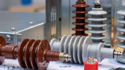
How to Choose Low Voltage Standoff Insulators in 2026
Start with the system’s maximum operating voltage, not just its usual reading. Check the insulator’s rated voltage and required clearances against the equipment design. Then consider mechanical load: busbars, cables, and vibration can place steady or sudden stress on mounting points. A rating that looks adequate on paper may not suit a heavy, unsupported conductor.
Temperature and moisture deserve equal attention. Enclosures near motors or outdoors may experience heat cycles, condensation, or direct spray. Review the material’s stated operating range, and inspect whether mounting hardware can resist corrosion. Dust, salt, and industrial residue can form conductive paths across surfaces, especially when damp. Small details matter. A clean indoor test condition may not reflect the cabinet after months of service. I would also revisit assumptions about cleaning frequency; it is easy to overestimate how often maintenance happens.
Tips: Match selection data to the actual installation. Note peak voltage, expected load, ambient temperature, and likely contaminants. If conditions are uncertain, consult a qualified electrical engineer and verify the manufacturer’s technical data before installation.
Assess voltage, mechanical load, temperature, moisture, and contamination before selecting an insulator.
Voltage classification reference: IEC low-voltage boundaries are up to 1,000 V AC and up to 1,500 V DC. These are classification limits, not recommended insulator ratings. Select an insulator for the actual system voltage, transient conditions, required clearances and creepage distances, and applicable standards. Also verify mechanical load, operating temperature, moisture exposure, and contamination level for the installation.
Low-voltage standoff insulators support conductors while keeping them electrically separated from panels and frames. Material choice affects heat tolerance, moisture resistance, and mechanical strength. Porcelain is rigid and handles heat well, but it can chip if struck during installation. Molded polyester or epoxy options are lighter and resist impact, though their temperature and outdoor limits vary by formulation. Check the datasheet, not just the material name.
Shape matters, too. Cylindrical bodies suit many straightforward panel layouts, while hexagonal profiles give a wrench a firm grip during assembly. Some designs include shoulders that help locate a conductor or maintain spacing. Measure the available clearance around terminals and nearby metalwork; a compact part can still leave awkward access for wiring. Details matter.
Mounting options include studs at both ends, a stud paired with a threaded insert, or a through-hole for a bolt. Match the thread, hardware, and support surface to the expected load, and avoid overtightening brittle bodies. Confirm creepage and clearance requirements for the actual equipment and environment. Dust, condensation, and heat can change performance over time. A tidy comparison chart may not capture those site conditions, so review the installation before choosing. I would not assume one shape fits every panel.
| Selection Factor | Option | Typical Characteristics | Best Suited For | Points to Check |
|---|---|---|---|---|
| Insulator Materials | ||||
| Material | Porcelain | Rigid ceramic with good heat resistance and electrical insulation. It is brittle and can crack if struck or over-tightened. | Fixed installations where heat resistance and dimensional stability are priorities. | Check for impact risk, surface damage, mounting stress, and the manufacturer’s voltage and environmental ratings. |
| Material | Steatite ceramic | Electrical ceramic commonly used for insulating supports; it is rigid and heat resistant but can be brittle. | Compact supports and assemblies exposed to elevated temperatures. | Confirm mechanical load limits and avoid point loading or excessive tightening force. |
| Material | Glass-reinforced thermoset (such as polyester or epoxy molding compound) | Rigid molded material with useful electrical and mechanical properties. Performance depends on the resin system, reinforcement, and formulation. | Electrical panels and equipment needing a molded, mechanically robust support. | Check temperature rating, moisture behavior, tracking resistance, flame rating, and chemical compatibility for the specific grade. |
| Material | Unfilled or reinforced thermoplastic (such as polyamide) | Can be lightweight and impact resistant; some grades absorb moisture, and properties vary with temperature and reinforcement. | Indoor equipment where ease of molding, weight, or impact tolerance matters. | Review the exact grade’s moisture absorption, operating temperature, creep behavior, flame rating, and electrical data. |
| Body Shape and Geometry | ||||
| Shape | Cylindrical or round | Simple, compact profile that can provide a uniform support surface. | General-purpose mounting when clearance and load are relatively straightforward. | Check diameter, height, contact area, and whether the part needs a wrenching feature. |
| Shape | Hexagonal body | Flat sides provide a convenient feature for holding or turning during installation. | Assemblies where tool access or controlled installation is useful. | Allow room for a tool; do not use the body shape as a substitute for the specified tightening torque. |
| Shape | Square or rectangular body | Offers a broad, flat footprint and can help resist rotation when fitted against a matching surface. | Panel or busbar layouts that need a defined orientation or wider support area. | Verify footprint, edge clearance, hole alignment, and the load direction. |
| Shape | Flanged or shouldered body | A flange or shoulder can locate the part against a surface and distribute contact over a wider area. | Mounting positions where alignment or a defined seating surface is required. | Confirm flange diameter, panel thickness, seating flatness, and clearance around adjacent conductors. |
| Mounting and Installation | ||||
| Mounting | Single-ended threaded stud | A projecting stud attaches to a panel, frame, or other support; the opposite end supports the conductor or assembly. | One-sided mounting where a fixed, compact attachment is needed. | Match thread diameter, pitch, usable thread length, panel thickness, and required tightening method. |
| Mounting | Double-ended threaded stud | Threaded ends on both sides allow attachment to a support and a separate component. | Assemblies that need a threaded connection at both the base and the supported side. | Check thread specifications at both ends, engagement length, and the load transferred to the insulator. |
| Mounting | Through-hole with bolt and nut | A hole passes through the insulator for fastening with separate hardware. | Installations where replaceable fasteners or through-bolting are preferred. | Check hole diameter, washer fit, bolt length, clearance, and the risk of crushing or cracking the body. |
| Mounting | Threaded insert | A metal insert provides a threaded attachment point within the insulating body. | Repeated assembly or designs that need a defined internal thread. | Confirm insert material, thread size, pull-out or torque limits, and electrical clearances around the insert. |
| Application Checks | ||||
| Electrical rating | Rated voltage and insulation performance | Low voltage is commonly defined as up to 1,000 V AC or 1,500 V DC, but this definition does not establish a component’s suitability for a particular installation. | Every application; select against the actual system and applicable equipment requirements. | Verify the component’s rated voltage, insulation resistance or dielectric data where specified, creepage distance, clearance, and relevant standards. |
| Mechanical rating | Load, vibration, and fastening stress | Allowable loads depend on the material, dimensions, mounting method, and direction of force. | Assemblies supporting busbars, terminals, or other parts subject to force or vibration. | Check the manufacturer’s load data, mounting instructions, fastener torque, and expected service conditions. |
| Environment | Temperature, moisture, contamination, and chemicals | Environmental performance varies by material and, for polymers, by specific formulation. | Indoor or outdoor equipment only when the selected part is rated for the installation conditions. | Review operating temperature, moisture exposure, pollution or contamination, UV exposure where applicable, and chemical contact. |
Selection note: Compare the exact part’s datasheet and applicable safety standards before installation. Material family and shape alone do not determine voltage, load, temperature, or environmental suitability.
For low voltage standoff insulators in 2026, begin with the equipment drawing, not a catalog photo. Record the required height, outside diameter, mounting-hole size, thread, and terminal spacing. A few millimeters can change conductor clearance or prevent a bracket from sitting flat. Small mismatches matter.
Then match the electrical ratings to the actual circuit. Check the rated voltage, insulation material, and applicable impulse or dielectric values in the product documentation. Also consider pollution, moisture, and temperature near the equipment. A dry indoor panel and a warm, dusty enclosure are not the same environment. Verify clearances against the equipment design, rather than assuming the insulator’s voltage rating settles every spacing question.
Mechanical loads deserve equal attention. Estimate conductor weight, vibration, and installation stress, then compare them with the insulator’s stated load capacity. Confirm that fasteners engage properly without forcing the part against a misaligned surface. In a cabinet, even a slight bend in a busbar can create pressure you did not plan for. It is easy to focus on voltage and overlook fit; I would recheck the drawing and datasheet before ordering. Leave room for manufacturing tolerances, too. That detail is often missed.
Verify standards and clearances before comparing materials. IEC 60664-1:2020 bases insulation coordination on factors including rated impulse voltage, pollution degree, and altitude. Nominal voltage alone does not set a safe air gap. Check the equipment’s applicable product standard, then record the required clearance and creepage distances in millimeters. NFPA 70B:2023 emphasizes a documented electrical maintenance program, so retain inspection results and the basis for your chosen intervals. IEEE Std 493-2007 also compiles industrial power-system reliability data; its broad failure statistics are useful context, not a lifespan prediction for one insulator. Small gaps matter.
Tips: Measure between actual conductive surfaces, not drawing centerlines. Check for sharp edges, loose hardware, dust, and moisture paths. Photograph the installed assembly and note ambient conditions. A neat reading can still miss a hidden crack.
During installation, confirm the standoff’s voltage rating, mounting-hole pattern, temperature range, and mechanical load against the assembly design. Use the specified torque; overtightening can stress brittle material, while a loose nut may allow movement. Inspect after installation and during scheduled maintenance. Look closely around bolt holes and beneath washers, where hairline cracks or tracking marks can hide. Record dimensions, visible damage, test results, and corrective work. If the site’s pollution or altitude differs from the design assumptions, recheck the insulation coordination rather than relying on a familiar clearance.