Choosing a Busbar Insulator in 2026 means balancing electrical performance, mechanical strength, operating conditions, and installation needs. A part that looks suitable on a drawing may behave differently in a crowded switchboard, where heat, vibration, dust, and limited clearance all matter. Small details count.
This guide introduces common busbar insulator types, including epoxy and other molded-resin designs, porcelain, thermoplastics, and composite options. It also explains how support-post and standoff forms fit different mounting layouts. Each material has trade-offs. Resin parts can offer compact shapes and useful insulation, while porcelain is valued for rigidity and heat resistance. Composite designs may reduce weight, but their performance depends on construction and application. There is no universal winner.
The right choice starts with the system’s voltage, busbar dimensions, expected load, ambient temperature, and exposure to moisture or contamination. Check clearances, creepage distances, mechanical loads, and the manufacturer’s ratings against the equipment design. Review relevant test documentation, too. Ratings vary by product and installation. That sounds tidy. Real panels are not. Access, fasteners, and replacement space can complicate an otherwise sound selection, so these practical details deserve a second look. This overview provides a grounded starting point for comparing options in 2026, while product datasheets and qualified engineering review should guide the final decision.
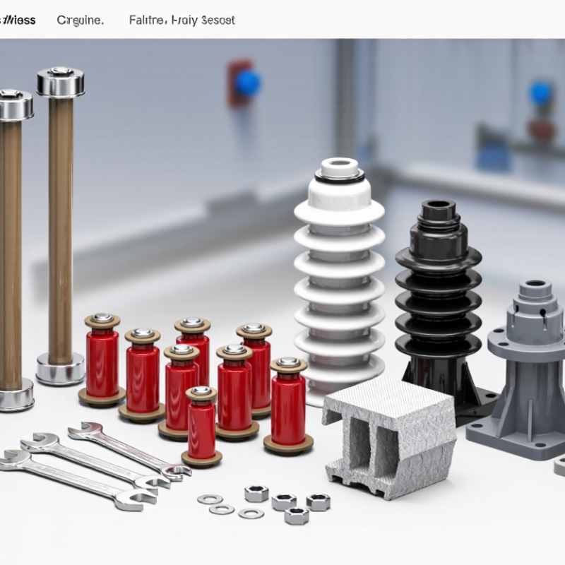
A busbar insulator is a nonconductive component that supports a metal busbar while separating it from grounded frames or neighboring conductors. It helps prevent unintended electrical contact and keeps designed clearances in place. Spacing matters. In a switchboard, these supports may hold copper bars above a steel panel, where vibration and electrical forces can gradually stress the assembly.
Insulators can be made from materials such as porcelain, epoxy resin, or engineered polymers. Their shape and mounting style vary: some are cylindrical standoffs, while others use molded ribs or brackets. The right choice depends on voltage, mechanical load, temperature, and the surrounding conditions. Dust, moisture, and pollution can affect surface insulation, so creepage distance—the path electricity could travel along the surface—also matters. A neat-looking part can still be unsuitable for its duty.
During inspection, technicians look for cracks, discoloration, tracking marks, and loose mounting hardware. These signs can point to heat, contamination, or mechanical strain. An insulator does not interrupt fault current like a protective device; it provides support and electrical separation. That distinction is easy to overlook. Selection and inspection should follow the equipment’s ratings and be handled by qualified personnel.
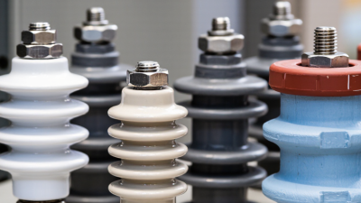
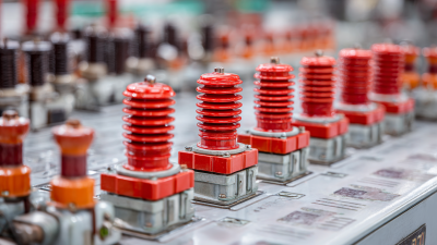
In 2026, molded epoxy-resin insulators remain common in low- and medium-voltage switchgear. They offer strong mechanical support, good electrical insulation, and compact shapes around copper or aluminum bars. Installers often choose them for rigid indoor assemblies, where dust and moisture can be controlled. But epoxy can crack under impact, so clearance, torque, and handling matter.
Polyester-based molded supports, including SMC and DMC types, are also widely used. They suit practical, cost-conscious assemblies, though heat and load ratings must match the installation. Porcelain remains an option where heat resistance and long service life are priorities, but its weight and brittleness can complicate fitting. Composite designs with silicone surfaces may help in damp or polluted environments.
No single type fits every panel. Grand View Research’s Electrical Insulation Materials Market report estimated the broader market at about US$10.4 billion in 2023, with continued growth projected through 2030. That figure covers insulation materials across many applications, not busbar insulators alone.
A useful selection starts with voltage, short-circuit forces, operating temperature, and the actual enclosure conditions. Small details matter.
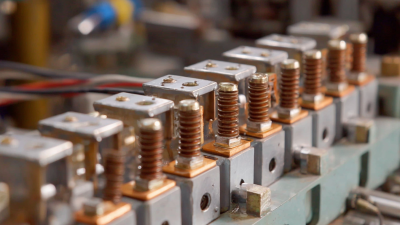
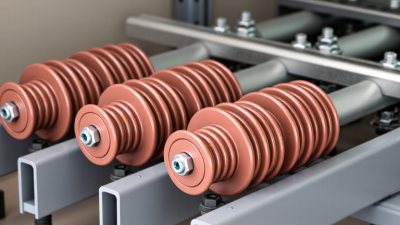
Support insulators carry busbars while resisting weight, vibration, and short-circuit forces. They often sit beneath horizontal copper bars, with metal fittings fixed to a panel or frame. Standoff insulators serve a related but simpler role: they hold a live conductor away from grounded surfaces. Think of a vertical bar held several centimeters from a steel enclosure. That gap matters. IEC 62271-1 lists a 75 kV peak lightning-impulse withstand level for common 12 kV-class equipment insulation coordination. The required level depends on equipment ratings and design, not on the insulator label alone.
Feed-through insulators pass a conductor through a grounded partition, enclosure wall, or barrier. Their design must insulate the conductor and seal or support the passage, so mounting details differ from a plain standoff. In practice, check voltage class, creepage distance, ambient pollution, temperature, and mechanical loading against the equipment specification. IEC 62271-1 provides rated insulation levels for high-voltage switchgear; IEC 60664-1 addresses insulation coordination at low-voltage levels. These standards give useful selection data, but they do not replace application-specific checks. A detail engineers sometimes underestimate is busbar movement under fault forces. A neat fit can still be the wrong fit.
| Insulator Type | Primary Function | Typical Installation | Common Materials | Key Selection Considerations | How It Differs |
|---|---|---|---|---|---|
| Busbar Support Insulator | Mechanically holds a busbar in position while electrically isolating it from its mounting structure. | Mounted between a busbar and a panel, frame, or other support surface. | Commonly molded thermoset materials, such as polyester-based compounds, or porcelain. | Check the required electrical ratings, mechanical loading, creepage distance, temperature range, and mounting arrangement. | A broad functional category: it describes an insulator that supports a busbar, rather than one specific shape. |
| Standoff Insulator | Supports a conductor at a specified distance from a grounded surface or another component. | Often fixed to a panel or enclosure, with the busbar attached to its top or side. | Commonly molded insulating polymers or porcelain, depending on the application. | Consider stand-off height, mounting thread or hardware, conductor loads, insulation level, and environmental exposure. | Emphasizes the physical spacing provided. A standoff is often used as a busbar support, so the terms can overlap. |
| Feed-Through Insulator | Provides insulation and mechanical support where a conductor passes through a panel or barrier. | Installed through an opening in an enclosure wall, partition, or insulating barrier. | May use molded insulating material or porcelain, with conductive terminals or inserts where required by the design. | Verify the conductor interface, barrier thickness, sealing needs, electrical clearances, and specified voltage and current ratings. | Designed around a passage through a barrier; unlike a basic standoff, it manages the conductor-to-barrier interface. |
| Post Insulator | Provides a relatively rigid insulating support for a busbar or other conductor. | Typically mounted upright or horizontally between a structural base and a conductor clamp or fitting. | Commonly porcelain or molded composite insulating materials. | Assess cantilever and other mechanical loads, mounting orientation, pollution conditions, and the applicable electrical ratings. | Usually has a post-like form and is selected where a defined support height and mechanical strength are needed. |
| Busbar Spacer or Separator | Maintains separation between adjacent busbars or between conductors in an assembly. | Placed between or around conductors, often as part of a busbar support arrangement. | Commonly molded insulating polymers or other materials specified for the assembly. | Check spacing, conductor geometry, temperature capability, short-circuit forces, and compatibility with the assembly design. | Primarily controls spacing between conductors; it may not provide the same panel mounting function as a standoff. |
Selection note: “Support,” “standoff,” and “post” may describe overlapping functions or shapes. Confirm the required voltage and current ratings, clearances, creepage distance, mechanical loads, material suitability, and applicable standards for the complete assembly. Ratings and dimensions vary by design; this table is a general comparison, not a product specification.
Busbar insulators are commonly made from glass-reinforced polyester, epoxy resin, or molded compounds such as BMC and SMC. These materials combine electrical insulation with mechanical strength. Glass fibers help a molded support resist bending when busbars carry heavy loads. Epoxy can provide a rigid, stable structure, especially where precise dimensions matter. The exact formulation affects heat resistance, moisture behavior, and long-term performance.
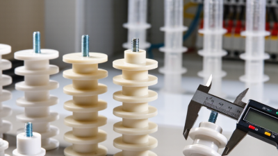
Ceramic and porcelain are also used, particularly where heat and dimensional stability are important. They can tolerate high temperatures, but their brittleness makes impact damage a practical concern. Some designs use engineering plastics, including polyamide, when lighter weight and easier molding are useful. Their performance depends on temperature, humidity, and the grade selected. Details matter.
A material should match the installation’s voltage, operating temperature, pollution level, and mechanical loading. For example, a support near a warm enclosure may need better heat resistance than one in a clean, cool cabinet. Manufacturers’ published ratings and relevant test data help confirm suitability. No material is perfect. Even a strong resin can age poorly if exposed to conditions it was not designed to handle, so selection deserves careful review.
Choosing a busbar insulator starts with electrical duty, not catalog shape. Match its rated voltage and impulse withstand to the system, then check creepage distance for pollution, humidity, and altitude. A dry indoor panel and a coastal switchroom need different protection. Epoxy supports offer rigidity and compact spacing; polyester molding may suit cost-sensitive assemblies, while porcelain tolerates heat but can crack under impact. Small details matter. Check the actual temperature near terminals, not just the room temperature. IEC 61439-1:2020 requires temperature-rise verification for low-voltage assemblies. Select a support validated within the intended assembly design.
Mechanical performance matters too. Fault-current forces can crack supports or loosen bolts, even when normal-load checks pass. Check the assembly’s short-circuit rating and test evidence; material name alone is not enough. For outdoor use, request evidence for UV exposure, moisture, and thermal aging. The IEA’s 2023 Electricity Grids and Secure Energy Transitions report places annual grid investment near $300 billion. Its climate-aligned pathway calls for more than $600 billion yearly by 2030. That expansion underscores the value of repeatable qualification, but it does not identify one best insulator material. Compare drawings, test conditions, and replacement access. Real sites are rarely that tidy.
This chart compares indicative dielectric strength ranges for common insulating materials. The bars show each range’s midpoint; actual values depend on material grade, thickness, temperature, and test method.
Choose an insulator by considering the system voltage, required creepage and clearance distances, operating temperature, mechanical loads, contamination, moisture, and applicable standards. Material dielectric strength alone does not determine a safe voltage rating; confirm specifications with the component manufacturer and a qualified electrical engineer.