How to Choose the Right Electrical Standoff Insulator 2026?
Choosing the right Electrical Standoff Insulator in 2026 requires more than comparing voltage ratings. The correct component must match the conductor spacing, mounting method, temperature range, humidity, vibration, and contamination level. A small ceramic standoff inside a dry control cabinet faces different risks from a polymer insulator near salt air. Surface tracking may begin quietly. Heat can also weaken the mounting point over time.
Dr. William A. Thue, an electrical insulation engineer and author, offers a practical reminder: “The best insulation is not simply the one with the highest voltage rating; it is the one that survives the actual environment.” This principle should guide every specification review. Check creepage distance, clearance, dielectric strength, mechanical load, and material stability. Then examine the real installation, not only the catalogue drawing. A part that passes a laboratory test may still perform poorly when dust settles on its surface.
Details matter.
Reliable selection should reference applicable IEC or UL requirements, supplier test reports, and documented production controls. Glass, porcelain, epoxy, and reinforced polymer materials each behave differently under heat and moisture. Some choices remain uncertain until tested under realistic conditions. That is worth admitting. Engineers should inspect samples, confirm thread dimensions, and review failure evidence before approving a large order. The right Electrical Standoff Insulator is therefore a balanced decision between electrical safety, mechanical durability, environmental resistance, and verified manufacturing quality.
What Is an Electrical Standoff Insulator?
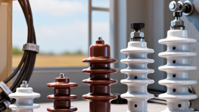
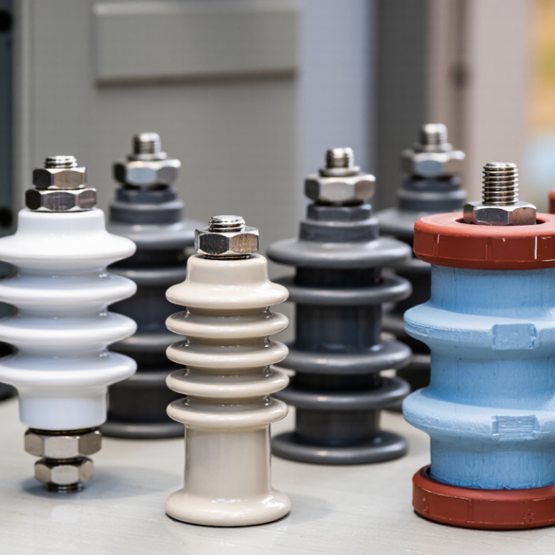
An electrical standoff insulator is an insulating support that holds a conductor away from a panel, chassis, or grounded surface. It maintains electrical separation while carrying mechanical loads. Common designs use ceramic, thermoplastic, or composite materials. Each material reacts differently to heat, moisture, vibration, and contamination.
The insulator’s shape creates clearance and creepage distance. Clearance is the shortest air gap between conductive parts. Creepage follows the insulating surface. Both distances must suit the working voltage and installation environment.
A dusty factory or humid enclosure may require more surface distance. Small details matter. A sharp metal edge can damage the insulator during tightening.
Choosing the right type requires checking voltage, current-related heat, mounting thread, load, and temperature range. The insulator does not normally carry operating current, but nearby heat can weaken it. Mechanical stress also deserves attention. A tall standoff may save space, yet it can bend more easily under cable weight or vibration. That trade-off is easy to miss.
Review the technical datasheet and applicable electrical standards before installation. Confirm torque values rather than relying on feel. Over-tightening can crack brittle materials. Under-tightening can allow movement. Neither result is acceptable. A part may look suitable on a workbench but fail after moisture, dust, and repeated thermal cycling. Selection should include inspection conditions, not only ideal laboratory ratings.
Which Materials and Designs Fit Your Application?
How to Choose the Right Electrical Standoff Insulator 2026?
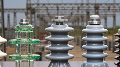
Material choice should follow voltage, temperature, moisture, and mechanical load. Ceramic suits high heat and strong dielectric performance. Epoxy and glass-filled polyester offer lighter, machinable alternatives. PTFE handles chemicals well, but its creep under continuous pressure deserves attention. It is not flawless.
Grand View Research’s 2024 electrical insulator analysis projects steady market growth through 2030, driven by grid upgrades and industrial electrification. That trend increases demand for compact, reliable insulation. Yet market growth does not replace application testing. A part rated for 10 kV may perform differently beside sharp metal edges or in humid air.
Design details often decide reliability. Choose threaded standoffs for secure panel mounting and repeatable assembly. Use shoulder designs when creepage distance must increase around a mounting hole. Feed-through styles fit conductors passing between isolated sections. For polluted or damp environments, prioritize longer creepage paths and sealed interfaces. IEC 60664-1 remains a useful reference for insulation coordination, including clearance and creepage evaluation.
Check torque limits, thermal cycling, and surface tracking resistance. In practical testing, a loose washer can create more trouble than an undersized body. I would also question catalog ratings without test conditions. Voltage, altitude, contamination, and cable weight should be documented before approval. The best design is rarely the largest one.
How to Check Safety, Standards, and Installation Conditions
How to Choose the Right Electrical Standoff Insulator 2026?
Safety starts with the complete installation, not the insulator alone. NFPA’s Home Structure Fires report found electrical distribution and lighting equipment involved in 31% of home fires from 2016 to 2020. Select a standoff by working voltage, impulse voltage, pollution degree, and altitude. IEC 60664-1 uses these conditions to determine required creepage and clearance distances. Do not copy a distance from an old drawing. The environment may have changed.
Check the material’s electrical and thermal evidence. A suitable technical file should identify dielectric strength, insulation resistance, temperature rating, and comparative tracking index. For polymer parts, review the UL 94 flammability classification, such as V-0, under the correct material thickness. Ceramic options can tolerate heat well, but they may crack after excessive tightening. Small defects matter.
Installation needs equal attention. Keep mounting surfaces clean, dry, and free from sharp burrs. Confirm the bolt, washer, thread engagement, and tightening torque. Excessive torque is a common mistake. It can deform polymer bodies or create hidden stress in brittle materials. Inspect creepage paths after assembly, especially near metal edges and cable terminals. Humidity, dust, vibration, and condensation deserve testing. I have seen a technically compliant part fail because water collected beneath it. Record inspection results, test conditions, and lot traceability. Recheck the design when voltage, enclosure, or pollution conditions change.
How to Choose the Right Electrical Standoff Insulator in 2026
Compare the nominal major diameters of common ISO metric mounting threads used with electrical standoff insulators. Thread size alone does not determine electrical safety; also verify creepage distance, clearance, material performance, voltage rating, and installation torque.
Selection check: Match the thread size to the mechanical assembly, then check insulation coordination according to IEC 60664-1, comparative tracking performance using IEC 60112 where applicable, dielectric strength using IEC 60243-1, and enclosure protection using IEC 60529 where relevant. Confirm the manufacturer’s actual dimensions and installation limits before use.