Leave Your Message
Selecting a Standoff Insualtor in 2026 begins with the conditions it must withstand. A unit beside a warm transformer may face heat, vibration, and dust. One mounted outdoors may also encounter moisture, ultraviolet exposure, and sudden temperature changes. The right choice depends on the actual installation, not just a catalog’s voltage rating.
This guide examines working voltage, material, dimensions, mounting method, and environmental exposure. It also considers creepage distance, clearance, mechanical load, and the hardware surrounding the insulator. Small details matter. A metal washer can change a stress point; a poorly supported cable can introduce persistent side force. Specifications should be checked against the manufacturer’s data and the assembly’s operating conditions. Then checked again.
No source material or verifiable expert quotation was provided, so I cannot responsibly attribute a statement to a named industry expert. The practical principle remains clear: choose for the complete application, not one impressive number. Even careful selection has limits. Installation quality, contamination, and aging can alter performance over time. This guide offers a structured way to compare options, identify questions for suppliers, and avoid assumptions that look harmless on a clean drawing but fail in the field.
How to Choose Standoff Insulators in 2026
Understanding the Role and Types of Standoff Insulators
Standoff insulators support busbars and conductors while separating energized parts from grounded surfaces. They also carry mechanical loads from cables, vibration, or switching forces. Small parts. Critical job. Their surface creepage path helps limit leakage when dust, salt, or moisture collects. A clean indoor cabinet and a damp outdoor enclosure do not present the same conditions.
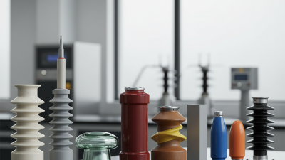
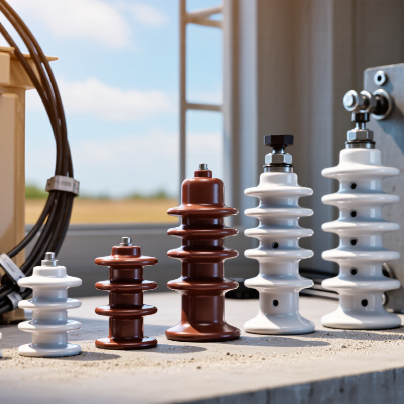
Common options include porcelain, epoxy resin, and composite materials. Porcelain offers strong heat and weather resistance, while epoxy designs can provide compact shapes for enclosed equipment. Composite units may reduce weight, but material alone does not determine suitability. Shape, mounting method, surface condition, and expected load all matter. The IEA’s 2023 report Electricity Grids and Secure Energy Transitions estimates that 80 million kilometres of grids must be added or refurbished by 2040. That scale makes dependable component selection important, though the report does not assess insulators specifically.
For a practical comparison, check operating voltage, impulse withstand, mechanical load, creepage distance, pollution exposure, and available mounting space. Confirm that ratings match the installed conditions, not just the product sheet’s ideal test environment. A high voltage rating is not a complete answer. I would also question whether cleaning and inspection access are realistic; that detail is easy to overlook.
| Type or Selection Factor | Typical Construction or Role | Key Advantages | Important Considerations | Common Applications |
|---|---|---|---|---|
| Porcelain standoff | Rigid ceramic body, often glazed, with threaded inserts or mounting hardware. | Good electrical insulation; resists heat, ultraviolet exposure, and many outdoor weather conditions. | Ceramic can crack or chip from impact, mishandling, or excessive mechanical stress. Check the specified cantilever and compression loads. | Electrical switchgear, busbar supports, and outdoor electrical assemblies where the design calls for a rigid ceramic insulator. |
| Glass standoff | Solid or molded insulating glass construction, used in designs specifically engineered for that material. | Non-porous glass surfaces can be readily inspected and cleaned; glass is electrically insulating. | Can be brittle and susceptible to impact damage. Availability, mounting design, and suitability for the operating environment vary by product. | Specialized electrical assemblies and equipment designed around glass insulation components. |
| Molded epoxy or other thermoset standoff | Rigid molded resin body, sometimes reinforced, with embedded or fitted metal inserts. | Can provide compact shapes, secure hardware integration, and good mechanical support when correctly designed. | Temperature limits, tracking resistance, moisture performance, and long-term aging depend on the resin formulation and product design. Review the manufacturer's ratings. | Indoor switchgear, control panels, busbar supports, and electrical equipment assemblies. |
| Silicone-rubber standoff | Flexible or molded elastomeric insulating body; some designs use a supporting core or integrated fittings. | Silicone materials can retain useful flexibility across a broad temperature range and can perform well outdoors when designed for the application. | Mechanical stiffness and load capacity differ from rigid ceramic or resin types. Confirm UV, pollution, temperature, and mounting suitability for the specific product. | Outdoor or specialized equipment where the selected silicone design is rated for the electrical and mechanical conditions. |
| Thermoplastic standoff | Molded plastic body, commonly used in compact assemblies and lower-stress support applications. | Can be lightweight, economical, and easy to form into practical mounting shapes. | Temperature, flame behavior, UV resistance, creep under sustained load, and electrical tracking performance are material- and product-specific. Do not assume suitability for high-voltage or outdoor service. | Indoor control panels, electronic assemblies, and equipment where the component's ratings match the design conditions. |
| Operating voltage and insulation level | The electrical conditions the insulator must withstand, including system voltage and applicable transient or test requirements. | Matching the component to the complete insulation design helps reduce the risk of flashover or breakdown. | Do not select by nominal voltage alone. Confirm rated voltage, withstand levels, clearances, and applicable equipment standards for the installation. | Every application; especially important in switchgear, substations, and busbar systems. |
| Creepage distance and pollution | Creepage distance is the shortest path along the insulating surface between conductive parts. | Appropriate surface-path design helps manage leakage current and flashover risk in contaminated or damp conditions. | Required distance depends on voltage, pollution severity, insulator profile, material, and applicable design rules. Salt, dust, and industrial deposits can affect performance. | Outdoor equipment and installations exposed to moisture, salt, dust, or industrial pollution. |
| Air clearance | The shortest distance through air between energized parts and between energized and grounded parts. | Adequate clearance helps prevent electrical discharge through air. | Check the finished assembly, not just the insulator dimensions. Voltage, altitude, field geometry, and applicable standards can affect required clearance. | Enclosures, busbar layouts, switchgear, and electrical panels. |
| Mechanical load and geometry | Includes mounting height, stud size, thread type, hole pattern, and forces from supported conductors or busbars. | Correct fit and load capacity support secure installation and stable conductor positioning. | Allow for static load, short-circuit forces, vibration, installation torque, and any relevant safety factors. Avoid applying bending loads beyond the product rating. | Busbar supports, electrical cabinets, and equipment subject to vibration or fault forces. |
| Environment and service temperature | Conditions such as indoor or outdoor location, humidity, temperature cycling, chemicals, UV exposure, and cleaning methods. | Environment-matched materials and designs can improve service life and reduce maintenance needs. | Check the component's documented temperature range and resistance to the actual contaminants and weather conditions; ratings are product-specific. | All installations, with particular attention to outdoor, corrosive, hot, or frequently cleaned environments. |
Selection note: Electrical and mechanical ratings vary by product and installation. Confirm the manufacturer's technical data, applicable local standards, and the requirements of the complete assembly before specifying a standoff insulator.