Leave Your Message

What Is a Ground Bar Standoff Insulator?

A Ground Bar Standoff Insulator is a small component with a critical responsibility. It supports a grounding bar while keeping the bar electrically separated from the metal enclosure. That separation may look simple, but it affects safety, durability, and installation accuracy.

Electrical educator Mike Holt has repeatedly emphasized, “Grounding and bonding are not the same thing.” This distinction helps explain why a Ground Bar Standoff Insulator matters. The insulator holds the ground bar in position without creating an unintended connection to the cabinet. Meanwhile, bonding conductors and approved hardware create the intended fault-current path.

In a real panel, the component may face vibration, heat, moisture, dust, and repeated maintenance. A cracked nylon body can weaken support. Incorrect spacing can expose the bar to the enclosure. Loose mounting hardware can create uncertainty during fault conditions. These details deserve attention.

The right insulator should match the bar design, mounting system, voltage environment, and manufacturer requirements. Material choice matters, too. Nylon, thermoset compounds, and other insulating materials can behave differently under heat and mechanical stress. A part that fits visually may still be unsuitable.

This article examines what a Ground Bar Standoff Insulator does, where it is installed, and how professionals evaluate one. It also considers common installation mistakes. Some assumptions need challenging. A larger insulator is not automatically safer, and a tighter connection is not always better. Careful selection, correct torque, and verified bonding practices remain essential.
What Is a Ground Bar Standoff Insulator?

Definition and Purpose of a Ground Bar Standoff Insulator

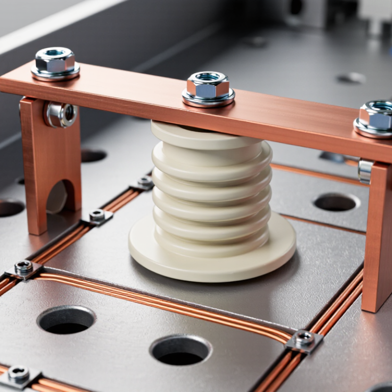
A ground bar standoff insulator is a nonconductive support that holds a grounding bar away from a metal panel or enclosure. Its purpose is both mechanical and electrical. It keeps the bar stable while preventing unwanted contact with the mounting surface. This separation helps control current paths during a fault and supports a cleaner, more reliable grounding layout.

The insulator is commonly made from durable materials that resist heat, moisture, and electrical tracking. Its size must match the bar, fasteners, and enclosure design. A qualified installer should confirm the required bonding arrangement before installation. In some systems, the ground bar must remain isolated from the enclosure. In others, a deliberate bonding point is required. Confusing these functions can create a serious safety weakness. It is easy to assume every bar should be bonded immediately. That assumption needs checking.

During inspection, look for cracks, loose hardware, discoloration, or compression damage around the standoff. A damaged insulator may still look acceptable from a distance. It may not provide dependable clearance under vibration or fault conditions. Keep conductors neatly arranged, and avoid placing excessive strain on the bar. Installation instructions and applicable electrical standards should guide the final decision.

Tips: Measure the mounting hole pattern before ordering parts. Use compatible washers and fasteners. Do not substitute ordinary plastic spacers without verifying their electrical rating. Record the inspection date. Small details matter.
What Is a Ground Bar Standoff Insulator?

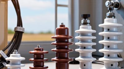
A ground bar standoff insulator is an insulating support that mounts a grounding bar to an enclosure or panel while electrically separating the bar from the mounting surface. The chart identifies the primary functions of the insulator. A value of 1 means the function is provided; 0 means it is not the function of the insulator itself.

Key Components and Materials Used in Its Construction

A ground bar standoff insulator separates a grounding bar from its metal enclosure while preserving a reliable electrical path. Its construction usually combines a threaded insert, molded insulating body, mounting washer, and fastening hardware. The grounding bar is commonly copper, with conductivity near 58 MS/m, or aluminum, near 35 MS/m, according to typical IEC material data.

The insulator material matters most under heat, vibration, and fault conditions. Glass-filled nylon offers useful mechanical strength and often shows dielectric strength around 15–25 kV/mm in ASTM D149 test data. Thermoset polyester and molded compound materials can provide stronger heat resistance.

Ceramic performs well at high temperatures, but it can crack after excessive tightening. A UL 94 V-0 rating only describes flame behavior. It does not confirm voltage endurance. IEC 61439 also requires enclosure assemblies to withstand temperature rise and short-circuit stresses, so the standoff must match the complete assembly.

Tips: Check the thread size, creepage distance, and torque value together. Never judge quality by appearance alone. Field inspections often find stress marks around the washer. That detail deserves attention. Copper oxidation, loose hardware, and undersized standoffs can increase resistance. ASTM D149 results also vary with moisture, thickness, and test temperature. Designers should request current test certificates, not rely on an old datasheet. A practical review should include thermal cycling and mechanical pull testing. Small errors remain possible, especially when drawings omit enclosure clearance.

How a Ground Bar Standoff Insulator Supports Electrical Safety

What Is a Ground Bar Standoff Insulator?

How a Ground Bar Standoff Insulator Supports Electrical Safety

A ground bar standoff insulator is a rigid support between a grounding bar and its mounting surface. It keeps the bar at a controlled distance from the enclosure. This separation helps prevent accidental contact with painted panels, sharp edges, or nearby conductors. The insulator also provides mechanical stability when several grounding wires terminate on one bar.

Safety depends on more than physical support. The grounding bar must remain electrically connected to the intended grounding system. The standoff should not interrupt that path. Instead, it positions the bar while maintaining required clearance and insulation from the cabinet. Correct material selection matters because heat, moisture, vibration, and chemical exposure can weaken unsuitable supports. A qualified installer should follow the equipment design and applicable electrical standards.

Small details deserve attention. Inspectors should check for cracks, loosened fasteners, damaged threads, and uneven mounting pressure. Conductors need clean contact surfaces and properly tightened terminals. Overtightening can damage the bar or distort the insulator. Under-tightening can create heat during a fault.

It is easy to overlook.

A useful inspection also confirms that the bar cannot shift during servicing. Labels and clear access reduce mistakes. In practice, a standoff may look simple, yet its dimensions influence spacing and installation quality. I would not treat every similar-looking part as interchangeable. A careful review is still necessary, especially when the panel operates in a wet, hot, or vibration-prone location.

What Is a Ground Bar Standoff Insulator? - How a Ground Bar Standoff Insulator Supports Electrical Safety

Data Dimension Technical Information Electrical Safety Contribution
Basic Definition A ground bar standoff insulator is an electrically insulating support that holds a grounding or bonding bar away from a metal enclosure, panel, cabinet, or mounting surface. It prevents unintended contact between the conductive ground bar and the enclosure while maintaining a controlled grounding layout.
Primary Function The component provides mechanical support, electrical isolation, and a fixed mounting position for the ground bar. A stable and insulated mounting arrangement reduces the risk of accidental short circuits, arcing, and damage caused by movement or vibration.
Typical Construction Common assemblies include an insulating body, threaded insert or stud, mounting hardware, and a compatible ground bar. The exact design depends on the enclosure and grounding system. Properly matched hardware helps maintain secure connections and prevents loose parts from becoming a source of heat or electrical faults.
Common Insulating Materials Frequently used materials include thermoset polyester, epoxy-based compounds, phenolic materials, and engineered thermoplastics. Material selection depends on voltage, temperature, mechanical load, and environmental exposure. Insulating materials provide dielectric separation and help limit leakage current between the bar and grounded metalwork.
Electrical Isolation The insulator separates the ground bar from the enclosure unless the design intentionally requires an electrical bond at a specified location. Isolation helps keep grounding, bonding, and neutral functions arranged according to the system design instead of allowing unintended current paths.
Ground Bar Material Ground bars are commonly manufactured from copper or aluminum and may include plated surfaces to improve corrosion resistance and connection performance. A suitable conductive material provides a reliable low-impedance path for fault current when properly sized and terminated.
Typical Applications Applications include distribution panels, control cabinets, switchboards, telecommunications enclosures, industrial control equipment, and equipment grounding assemblies. The support keeps grounding conductors organized, accessible, and securely connected within electrical equipment.
Mounting Arrangement Standoff insulators may be mounted using screws, studs, threaded inserts, or rail-compatible hardware. The mounting surface should be rigid, clean, and suitable for the intended load. Correct mounting reduces mechanical stress, conductor movement, and the possibility of loose connections during operation or maintenance.
Creepage and Clearance Creepage is the distance along an insulating surface, while clearance is the shortest distance through air. Required distances depend on system voltage, pollution level, insulation type, and applicable standards. Adequate spacing reduces the risk of surface tracking, flashover, and dielectric breakdown.
Voltage Consideration A standoff insulator must have a suitable dielectric rating for the equipment in which it is installed. There is no universal voltage rating; the assembly rating must be confirmed from the component and equipment documentation. Using an appropriately rated insulator helps prevent insulation failure under normal operating and transient conditions.
Temperature Consideration The selected material should withstand the expected continuous operating temperature and short-duration heating associated with fault currents. Temperature limits vary by material and design. Thermal compatibility helps prevent deformation, cracking, loss of insulation, and reduced mechanical strength.
Mechanical Load The insulator should be rated for the weight of the ground bar, connected conductors, installation forces, vibration, and possible electrodynamic forces during a short circuit. Adequate mechanical strength helps keep the bar and terminals in position during normal service and fault conditions.
Connection Quality Grounding conductors should be terminated with compatible lugs, clamps, or direct bar connections. Contact surfaces should be clean and fasteners tightened to the specified torque. Secure, low-resistance connections help carry fault current and reduce localized heating, voltage drop, and intermittent grounding.
Neutral and Ground Separation In many systems, the neutral bar and equipment grounding bar must remain separated in downstream panels, while the required bonding point is established at the designated service or system location. Correct separation helps prevent normal neutral current from flowing on equipment grounding paths and exposed metal parts.
Environmental Resistance Selection should consider humidity, dust, chemicals, salt spray, ultraviolet exposure, and indoor or outdoor installation conditions. Environmental compatibility helps preserve insulation performance and prevents corrosion-related increases in connection resistance.
Inspection Points Inspect for cracks, discoloration, tracking marks, loose hardware, corrosion, deformation, damaged threads, and contact between the bar and enclosure. Early detection of physical or electrical deterioration helps prevent insulation failure and unreliable fault-current paths.
Installation Practice Installation should follow the equipment design, applicable electrical codes, manufacturer instructions, conductor sizing requirements, and specified torque values. Following approved installation practices supports code compliance and helps ensure the grounding system performs as intended.
Testing and Verification Depending on the equipment, verification may include visual inspection, continuity testing of bonding paths, insulation checks where applicable, and torque verification. Testing confirms that intended conductive paths are continuous and that unintended contact or insulation damage has not occurred.

Safety note: Ground bar standoff insulators must be selected and installed according to the complete equipment design, applicable electrical codes, and verified electrical and mechanical ratings. De-energize equipment and use qualified personnel for inspection or maintenance.

Common Types and Installation Configurations

What Is a Ground Bar Standoff Insulator?

A ground bar standoff insulator supports a grounding bar while keeping it electrically separated from a metal panel. It usually combines a threaded stud, insulating body, and mounting hardware. The body may use porcelain, thermoset resin, or a molded polymer. Each material behaves differently under heat, moisture, and mechanical stress. Porcelain handles heat well but can crack under impact. Polymer parts are lighter and easier to handle. Resin types often provide strong electrical insulation in compact enclosures.

Common installation configurations include wall-mounted bars, panel-mounted bars, and insulated supports inside switchgear cabinets. Single-hole supports suit simple layouts. Two-hole supports resist twisting on longer copper bars. Installers should check bar weight, fault-current requirements, enclosure depth, and required clearance. The support must remain firm when cables pull sideways. A poor mounting position can create stress near the terminal connection. That detail is often underestimated.

Tips: Keep the insulator clean and dry. Tighten hardware to the specified torque. Do not let sharp bar edges touch the body. Verify isolation with approved test equipment before energizing. Follow local electrical codes and the equipment manufacturer’s instructions. In real installations, space is rarely perfect. Measure twice. A final visual inspection may reveal loose washers, uneven alignment, or an unsuitable fastener before these small issues become serious.

Selection, Inspection, and Maintenance Considerations

What Is a Ground Bar Standoff Insulator?

A ground bar standoff insulator supports a grounding bar while separating it from a metal enclosure. Its selection affects electrical clearance, mechanical stability, and long-term reliability. Choose a model rated for the system voltage, expected fault conditions, temperature range, and installation environment. Moisture, dust, chemicals, and vibration can change performance over time.

Physical fit matters too. Check the mounting-hole pattern, thread type, bar thickness, and required clearance before ordering. Creepage distance deserves attention, especially in damp panels. A part may fit perfectly and still provide inadequate insulation. That mistake is easy to make.

Inspection should begin with the power isolated by qualified personnel. Look for cracks, whitening, carbon tracking, loose fasteners, distortion, and discoloration around the bar. A flashlight can reveal fine surface damage. Check that conductors are secure and that no strand touches the enclosure unintentionally. Follow the specified torque values; excessive force can damage the insulator, while low torque may create heat.

Maintenance is usually simple but should be documented. Remove dust with a dry, non-abrasive method, then inspect areas near cable entrances for moisture or residue. Do not use solvents unless their compatibility is confirmed. In high-vibration equipment, recheck mounting hardware during scheduled service. Electrical continuity and bonding tests should follow the applicable code and site procedure. A visual inspection alone is not enough. Conditions change, and older insulating parts may need replacement even when they look acceptable.