Leave Your Message
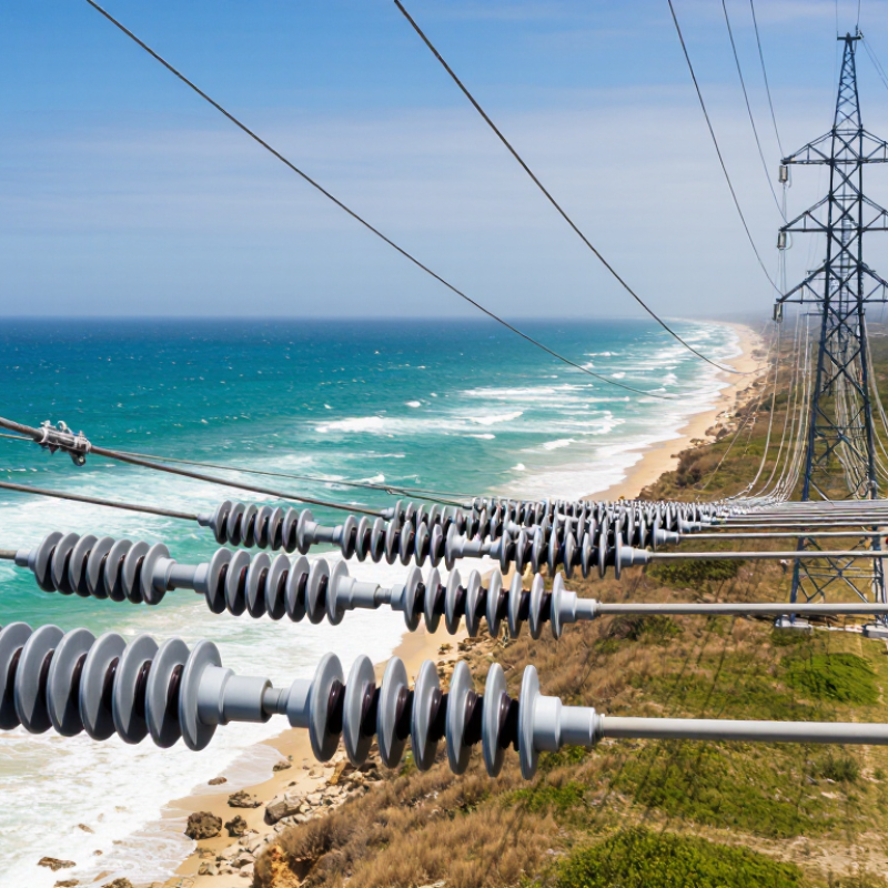
Choosing the right Composite Insulator begins with the line’s actual environment, not a product brochure. A 110 kV transmission line beside a coastline faces salt deposits, strong wind, ultraviolet radiation, and frequent wetting. A dry inland corridor may create different stresses, including dust, heat, and sudden temperature changes. These details influence housing material, creepage distance, mechanical strength, and fitting design.
Prof. R. Hackam, a respected researcher in polymeric insulation, expressed a valuable engineering principle: “Insulation performance is determined by service conditions, not by appearance.” That view remains highly practical. A smooth silicone surface may look convincing, yet the selected Composite Insulator must still satisfy electrical, mechanical, and environmental requirements. Engineers should review leakage-current behavior, hydrophobicity recovery, corona control, routine-test records, and long-term aging evidence. Standards such as IEC 61109 and IEC 62217 provide a reliable technical foundation. They do not replace field judgment.
Small details matter. Check the crimped end fitting, seal condition, shed spacing, and manufacturer’s quality-control process. Ask whether the design has operated under comparable pollution and ice conditions. A lower purchase price can become expensive after repeated inspections or premature replacement. That is not always obvious.
No checklist is perfect. Installation errors, unexpected contamination, or unusual weather can still change performance. The strongest choice combines laboratory results, supplier experience, independent verification, and local maintenance knowledge. A capable engineer should question attractive claims, document assumptions, and remain willing to revise the specification when field evidence disagrees. That cautious habit protects reliability better than choosing by brand reputation alone.
How to Choose the Right Composite Insulator?
What a Composite Insulator Is and Where It Is Used
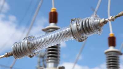
A composite insulator combines an epoxy or fiberglass-reinforced core with a weather-resistant polymer housing. The core carries mechanical loads. The outer sheds resist moisture, pollution, sunlight, and electrical tracking. Compared with traditional ceramic units, composite designs are lighter and easier to handle during installation. They also perform well where space, transport, or maintenance access is limited.
Composite insulators are used on overhead transmission and distribution lines, substations, railway electrification systems, and compact electrical equipment. In coastal areas, industrial zones, and dusty regions, their shed shape helps control leakage current across contaminated surfaces. Field engineers often examine salt deposits, bird activity, wind exposure, and temperature changes before choosing a design. The application matters more than appearance.
Selection should match system voltage, mechanical loading, pollution severity, required creepage distance, and local weather conditions. The insulator must also meet recognized electrical and mechanical testing requirements. A clean catalog choice can still be unsuitable in a harsh environment. Installation torque, conductor movement, and damaged sheds deserve attention. Small mistakes matter. It is easy to overtrust laboratory data. Real service conditions are rarely perfect, and inspection records should influence the final decision.
| Composite Insulator Type | Basic Construction | Typical Applications | Common System Voltage Range | Typical Overall Length | Typical Creepage Distance | Typical Mechanical Rating | Key Selection Considerations |
|---|---|---|---|---|---|---|---|
| Pin Insulator | A fiberglass-reinforced polymer (FRP) core with a silicone-rubber housing and sheds, usually mounted on a metal pin. | Compact overhead distribution lines, crossarms, and line sections with limited conductor movement. | 11–33 kV | 300–700 mm | 320–1,000 mm, depending on pollution severity | Typically 10–20 kN transverse or cantilever strength | Check conductor size, crossarm geometry, lightning exposure, pollution level, and required leakage distance. |
| Suspension Insulator | A flexible FRP rod with weather sheds and metal end fittings designed to support the conductor in suspension. | Transmission lines, substations, and dead-end structures where the conductor load is mainly tensile and vertical. | 33–220 kV; higher voltages use longer strings or multiple units | 500–2,500 mm | 800–7,500 mm, selected by insulation and pollution requirements | Typically 70–300 kN tensile strength | Verify rated tensile load, arc distance, coupling dimensions, corona control, and required creepage distance. |
| Tension or Dead-End Insulator | A high-strength FRP core and polymer housing with end fittings arranged to carry the full conductor tension. | Terminal towers, angle towers, river crossings, long spans, and line sections requiring conductor anchoring. | 33–500 kV | 600–5,000 mm | 1,000–15,500 mm, depending on voltage and environmental conditions | Typically 70–400 kN tensile strength | Calculate everyday tension, maximum working tension, wind and ice loading, hardware compatibility, and safety factor. |
| Line Post Insulator | A rigid composite column with a polymer weather shed system and a reinforced core that resists cantilever loads. | Distribution and transmission lines, compact structures, jumpers, and locations where a rigid support is preferred. | 11–230 kV | 300–2,000 mm | 400–6,200 mm, depending on the design and pollution class | Typically 2–20 kN·m cantilever strength | Compare cantilever, torsional, and compression loads; also check conductor swing, fitting dimensions, and clearance. |
| Station Post Insulator | A rigid polymer-insulated post assembly mounted on a substation support structure or steel base. | Busbars, disconnectors, circuit-breaker connections, and outdoor substations. | 11–245 kV | 300–2,500 mm | 400–7,750 mm, depending on insulation coordination | Typically 2.5–20 kN cantilever strength | Check short-circuit forces, seismic loads, bending strength, terminal arrangement, and the specified highest voltage for equipment. |
| Hollow-Core Composite Insulator | A hollow FRP tube covered with a polymer housing, allowing internal equipment or insulating gas to pass through the center. | Instrument transformers, cable terminations, bushings, surge arresters, and other high-voltage outdoor equipment. | 72.5–550 kV | 600–4,500 mm | 1,800–14,000 mm, depending on voltage and pollution conditions | Specified by bending, pressure, and internal equipment requirements | Confirm internal pressure, sealing, bending load, partial-discharge performance, creepage distance, and interface dimensions. |
| Railway and Traction Insulator | A compact composite insulating body with reinforced polymer support and weather-resistant sheds. | Overhead contact systems, feeder supports, return-current arrangements, and railway substations. | 1.5–25 kV AC or DC systems, depending on the railway network | 150–1,200 mm | 250–3,700 mm, depending on contamination and operating voltage | Application-specific mechanical rating, commonly 5–50 kN | Consider vibration, mechanical impact, ice, salt contamination, tracking resistance, and the required electrical clearances. |